Chapter 2: From the sleeping beauty to wedding day


After disassembling the bike so far that only framework is left like shown on the left picture, it was time to get rid of the stains from the extinguishing foam and the fire smoke. It was a hard
time cleaning and took alot of patience and time. All the plastic parts (except for the main fairings) had to be thrown away, because of their changed colour and awful smell as a result of the
fire. The cleaned framework got wrapped in bubblewrap for protection. Now it was time for a few years of hibernation until a matching donator would be found. In the beginning of 2015 it was time
to wake up again since a crashed caponord with only 13000km was found!
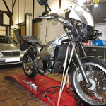
As a first step this bike was also torn apart into it's pieces. Just like on the other Caponord all the disassembled parts also had to cleaned. Now it was time to slowly wake the motorcycle again and bring it back to life. Time to begin the rebuilding. As a first step the wiring loom had to be put on. To get sure that all the plug connectors were in the right place some electric parts like the lower tail fairing where mounted. On this fairing you will find some relays aswell as the ECU, this makes it a lot easier finding the right position of the wiring loom.
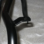
After the wiring loom is hooked and fixed to the bike, it's time for the wedding when the framework meets the motor (picture on the right).
Chapter 3: Upgrades and wear parts


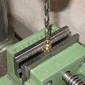
After motor and all the auxiliary equipment was fixed to the bike, it was time to have a look at the wear parts. First of all the bike supposed to get a pair of new tires. Checking the wheel bearings showed that they had to be renewed. That was proven having a look at the backside of the bearing after it's removal (see figure). Since the brake discs on the front wheel where already missing when we bought the bike, we had to get replacements. Having the goal rebuilding the bike as close as possible to the original, we had to get a set of new original discs, washer, screws and so on. The brake disc for the back wheel was used from the crashed bike, since it was in great condition, because of it's low mileage (13000km).
We also took the chance at that point replacing all the rubber hoses from the brake- and the clutch- system by using overbraided stainless steel brake lines from our shop. After brake system,
tyres and so on where overworked only one thing was left to do.....the chain kit! Since the whole bike is getting a work over, there was no way using a used chain kit. So we had to get a new one
and chosen the high class premium quality using a RK XW-ring chain and hardened sprocket wheels from France Equipment which convince with their great treatment and durability. We have been using
these sets for almost 20 years now and can only report good stuff about it. Any request on those set's, don't mind to ask we can get them for any bike so you can buy them in our shop.


During the mounting of the compensation tank we did not use the gray plastic cover as a protection. Instead we used one of our carbon fiber cover we produce ourselves using the resin transfer
moulding method. The first picture shows a part coming directly out of the mould not trimmed yet. The second picture shows it already mounted on the bike. The last two pictures show the bike
status after the work was done.
Chapter 4: Final touch and elimination of small issues (fuel line)
Since the main part of the bike was rebuild, it was time to get rid of some small issues such as the plastic fuel line connectors. Unfortunatly many motorcycle manufacturers use the plastic connectors in production to save money. Although most of the motocycle riders would prefer better quality and be willing to pay the small additional costs. The plastic has the bad characterisic to become brittle as time passes. This leads to small cracks und finally lets the connector brake which can end up in a burning bike. But mostly they brake during the disassembling. Since the fuel lines are pressed on, you usually have to change the whole line. Most of the times the new line will have the plastic connectors again, so this ends up in becoming an endless circle. We wanted to avoid this, what is already been mentioned on our homepage. But this time we did some changes and we show more details.


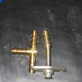

The throttle connector piece should get another connector which gets fixed by soldering. This allows us to use fuel lines from car suppliers. First we cut the pressed fuel line of the throttle
connector piece. As a new connector we used a four-way distributor used for air pressure supply. One end got cut off and then drilled so the throttle connector would fit in. Now the parts where
solderd together, on the buttom picture you see the mounted throttle connector. For a better protection the fuel line was covered with a corugated pipe. The fuel line was fixed to the connector
using a bracket also out of the air pressure supply.

Now only the new connectors are missing. But what matters and is important when looking for new connectors? Well, one of the manufacturers of those connectors is the company CPC, a company also
supplying a wide field of motorcycle manufacturers. Those connectors are also available as metal connectors. The quality of those connectors is outstanding but they still have a weak point. The
O-ring on the outside often get's damaged during assembly (picture on the right). This cause comes from fuel running over the O-ring during disassembly. The fuel vaporizes and the O-ring is dry.
This dry O-ring is not able to slide in the connector during the assembly. It sticks to connector and gets pulled out of the groove a little which leads to a pinched O-ring like seen on the right
picture. But if you already have those connectors mounted, there is a way in preventing this to happen. Before mounting, just spit a little on your fingers and rub it on the O-ring and now a easy
mounting without any problems is possible.
But we wanted avoid this problem with our connectors. That's why our connectors don't have a rubber O-ring on the outer rim. These have Viton sealings inside the valve so it can't be damaged during mounting. That also makes connecting very easy either dry or wet. Available in our shop for many motorcycles if wanted, so go ahead and ask for your bike.


Chapter 5: Final touch and elimination of small issues (R/R and wiring)


In the next step the Rectifier aswell as the wiring should be renewed. This important section was a little uncared from the producer. The wiring which connects battery and rectifier was designed to thin. That leads to greater resistance in the wiring, and also the connectors are simple cable shoes without any sealing against moisture. This is very critical especially in the area near the motor where the generator get's plugs into the wiring harness. Because besides the temperature of the motor the plug also gets moisture when driving in bad weather conditions what leads to corrosion in the end. This contact corrosion increases the electrical resistance and the result is a higher temperatur on the connector which can get so hot that it melts. You will find several bike on the internet where exactly that was leading to a burning bike.
That is why the wiring diameter was increased and the plugs where changed out using water resistant connectors. Also the rectifier itself was changed against a mosfet rectifier which works more efficient and cooler.
Chapter 6: High grade quality down to the core


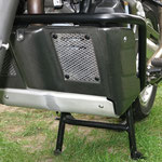
The search for the Rally Raid sumpguard protection was one of the hardest since there where only about 380 vehicles of this special edition build. But after a long period of time we were able to find one. To give it back the brilliance of the old days the paint was chemically removed und the part was sand blasted. Now it was time for a base coat with a following powder coating. Now the sumpguard had the same high quality coating we use for our motorcycle equipment. Have a look at the pictures, they say more than words. The new crash bars also gotten powder coated running through the same procedur. But why? Well a lot of motorcycle manufacturers and companies building motorcycles equipment don't use a base coat before powder coating as it's quite cheaper. Sometimes they even powder coat directly after welding the parts together without any cleaning (removing scale and so on). That leads to the result that those coatings mostly only last for a few years bevor they start to fall of. Something we wanted to avoid right from the start.
Chapter 7: A new dress for the bike


The painted fairings had clearly visible marks from the fire smoke and the extinguishing foam. We weren't sparing any effort on trying to remove those marks but it was impossible. So it was neccessary to give them a new paintjob. But to abide the Rally Raid design it should also be the two colour scheme. So first of all the parts had to be cleaned very well. That was followed by removing the decals und sanding the fairings. The chosen colours were silver and dark grey metallic. The selection of the different colour shades and their matching took over one hour sitting in the sun comparing paint cards with each other.
After that step was done the fairings first got their primer coat followed by the silver paint as the basic. To ensure that the separation of both colours match the fairing they had to be mounted to the bike. And to ensure it was in the same height as before also our other Rally Raid was brought to the painter so he could see were it should be. After that step the parts were taking of again and ready for the second colour.
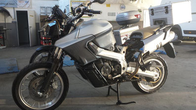

The result after the dark grey was applied can be seen on the upper left picture. Also a clearcoat was put on and sanded. Because now it was time to add the new decals to the bike, that's why the fairings had to be mounted again. And also the other Rally Raid was there again for better positioning of the decal. Then they came off for their final touch, a matt paintjob to cover the decals and give a slight shine. The detail picture below gives a little foretaste of the result.

Chapter 8: Upgrades to keep her up to date


The fully adjustable rear shock has aged in the past years, especially the spring got it's marks caused by the fire and extinguishing foam. So the decision was made to put in a new spring. Since the motorcycle is almost entirely used riding with a passenger, it was clear that the spring would have to have a progressive winding. That should ensure that there is enough spring range even with a higher load.


It was already planned for quite a while to construct and build a radiator protection.Since the rebuild Caponord should get one it was time to work on that issue. As always on our parts the top priority was a high corrosion protection. That's why we decided to use V4A stainless steel frame with a glass shot surface. The surface gives the part a noble finsih. For the mesh we used aluminium with a black powder coating for protection. It will be available in a couple of weeks in our shop.
Chapter 9: Further Upgrades & Renewel


Rebuilding the bike made new handguards neccessary. Since the handguards of the Moto Guzzi Stelvio were very similar to the ETV Caponord ones the decision was clear. But they cover up a little more, so it was neccessary to make some cut outs in order to give the throttle cables the needed space for a perfect function. (first picture on the left).
Since the motorcycle already had heated grips mounted which where now added by two heated seats, a small and easy to use control panel was needed! The task was to have only one control module for all three heating elements. At the time there is nothing on the market in that quality allowing the control of 3 heating elements. With the mounted one each heated source can now easily be turned on or off individually. And the heat intense is adjustable in 10 steps for each source. The control panel get's delivered as a complete unit including the wiring for grips and seats. They will be produced soon in a very exclusiv and small series and can be found over our hompage!
Over the years the weather left it's marks on some rubber parts on the bike. That made it neccessary to change some of those parts out, the example shows the rubber in the back of the headlight in the steering area. All that was needed was a universal rubber sheet, a cutting knife as well as a punch out. The original part was used as a template (right picture).
Renewing the isolation stickers on the inner side of the fairings was very similar. Since the originals where already taken off preparing the parts for painting they where used as patterns to cut out new ones out of a isolation sheet.
Chapter 10: Wiring the additional components


After the bike has sucessfully completed it's first test run, it was time to wire all the additional components such as the additional light systems, warning lights controller as well as the energy supply for the Topbox and the Tankbag. Of course, the additional energy supply was mounted that way that it is not visible when not in use. The used plugs were all AMP Superseal connectors to ensure the best weather protection.
Chapter 11: The heat is on....it's on the seat now
coming soon.....
more next weeks..........to be continued..........stay tuned.......